A four wire connection is made to eliminate the effects of the lead resistance.
Testing solar panels v vs i curve reverse bias.
Short circuit current isc flows with zero external resistance v 0 and is the maximum current delivered by the solar cell at any illumination level.
A larger fill factor is desirable and corresponds to an i v curve that is more square like.
How to test a 12 volt solar panel vs other voltages.
Fill factor is also often represented as a percentage.
At the knee of a normal i v curve is the maximum power.
A four wire connection is made to eliminate the effects of the lead resistance.
Simply touch the solar panel leads with the multi meter probes matching their corresponding polarity red to red black to black.
Figure 1 shows a typical i v curve the power voltage or p v curve that is computed from it and key points on these curves.
As most solar panels are 12 volts the solar panel test methods are basically the same.
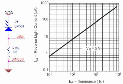
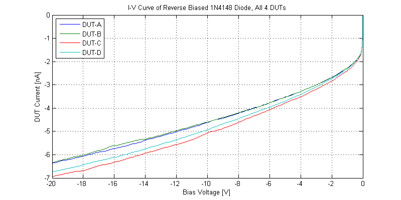
One method for determining the shunt resistance of the pv cell is from the slope of the reverse biased i v curve as shown in figure 5.
Open circuit voltage can vary depending on your solar panel but the readings we are usually looking for are in the range of 15 to 23v.
A linear sweep of the output voltage with a duration of 20 ms was applied in both the forward direction from short to open circuit and the reverse direction.
Some exceptions may apply based on panel type.
One method for determining the shunt resistance of the pv cell is from the slope of the reverse biased i v curve as shown in figure 5.
You will want to ensure that you place the positive to positive and negative to negative when attaching your multimeter to the connection on the back of your solar panel.
Efficiency η efficiency is the ratio of the electrical power output p out compared to the solar power input p in into the pv cell.
Testing the 12 volt solar panel.
Similarly the open circuit voltage voc is the potential that develops across the terminals of the solar cell when the external load resistance is very large figure 3.
Referring to figure 1 the span of the i v curve ranges from the short circuit current isc at zero volts to zero current at the open circuit voltage voc.
A solar cell or panel is connected to an smu as shown in figure 6.
Typical fill factors range from 0 5 to 0 82.
A solar cell or panel is connected to an smu as shown in figure 6.